Macintosh 512K Repair
I picked up this Macintosh 512K on a daytrip to Oregon to pick up a few TRS-80 Color Computers for prices fair enough to justify the reasonably short drive. The seller is a vintage computer enthusiast with a sizable collection of PCs and early computers who is trying to downsize. Everything I purchased is known to be in some state of “needing repair”. I’m always happy to have fresh projects, although it certainly doesn’t help shrink the project pile!
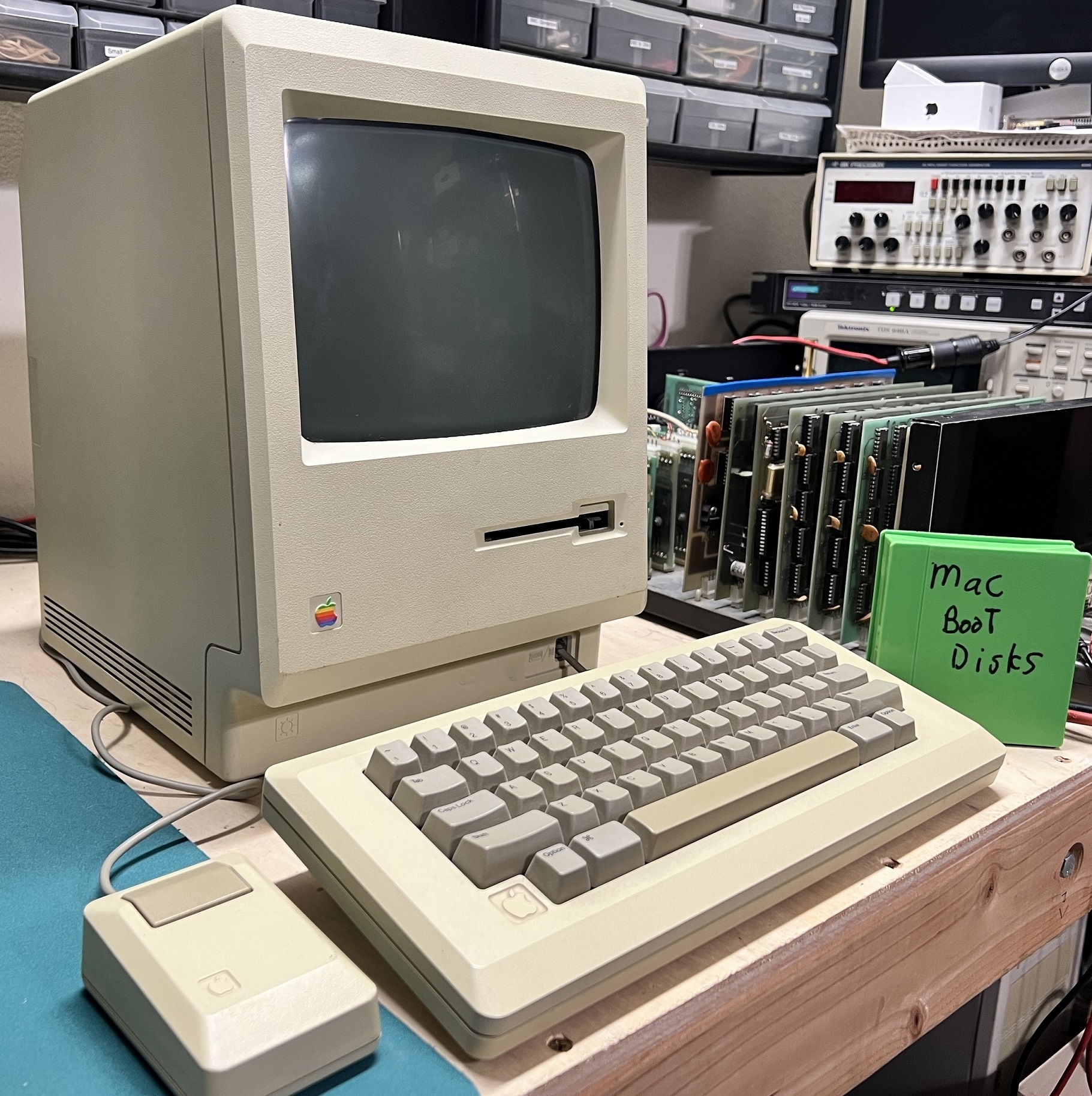
I’ve always wanted a Mac of this form factor. It’s reasonably self-contained, portable, and just so gosh-darn cute!

The seller had a couple of Macs for sale, and I believe they both had 512K badges on them. I decided on this particular unit as its shell was less yellowed, and it became apparent that it had some upgrade work when I spotted a full 50-pin Centronics-style SCSI connector mounted on a bracket in place of the battery cover.

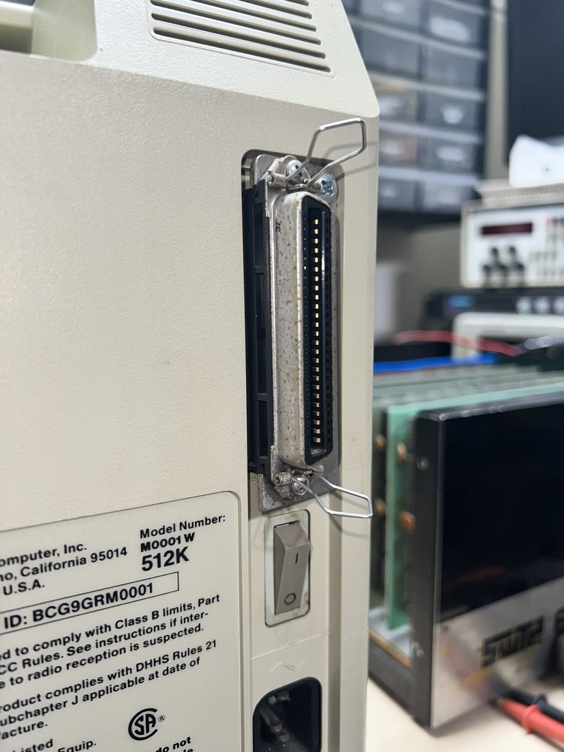

You can see why it caught my eye. That SCSI connector sticks out like a sore thumb!
Behind the SCSI connector bracket, the battery had leaked expectedly. There’s a little bit of corrosion on the shell of the SCSI connector and other system connectors, but nothing seems corroded to the point of warranting immediate replacement.
I had to pull the back of the computer off very carefully to avoid damaging the internal SCSI ribbon cable.
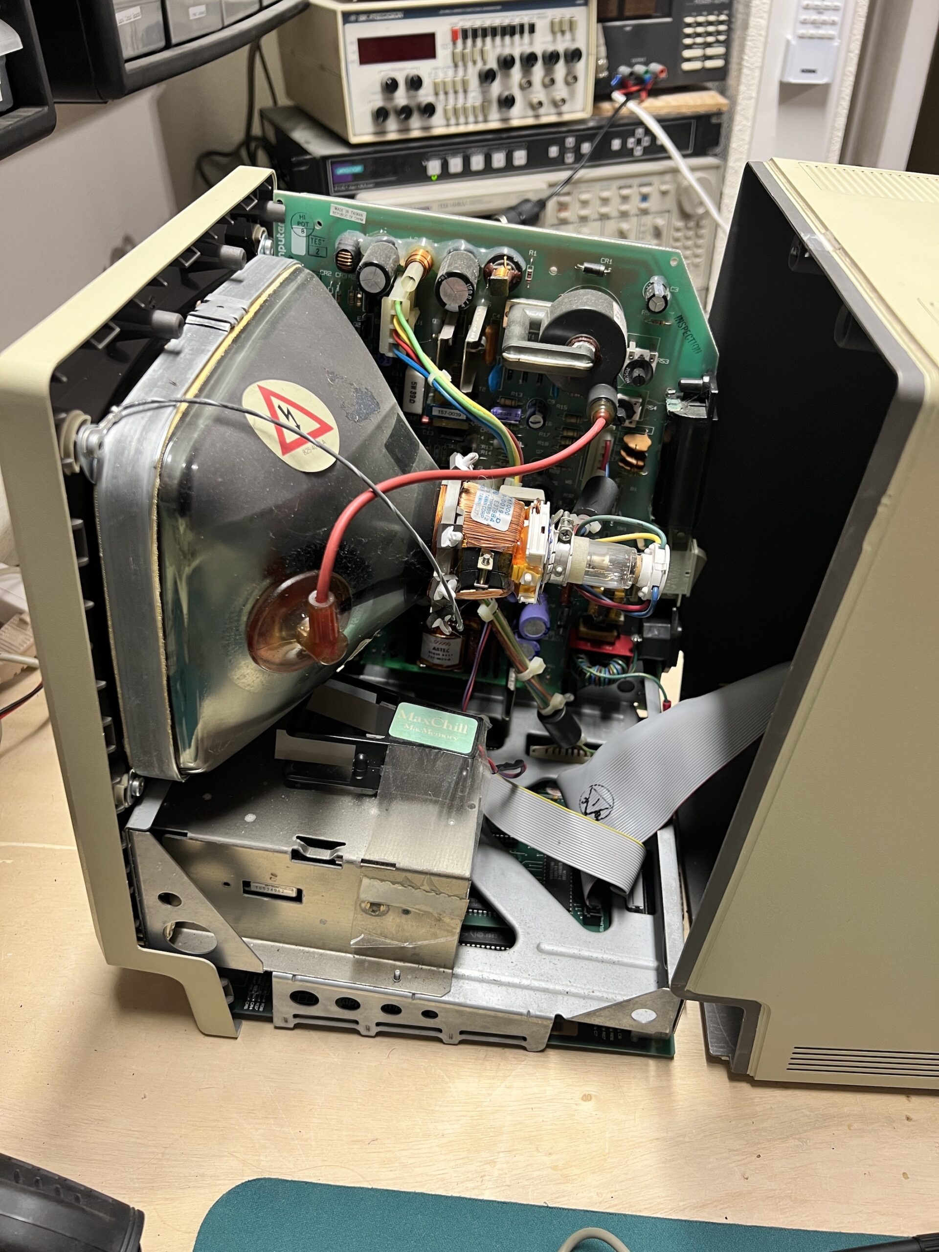
After pulling the computer apart, another aftermarket modification was immediately apparent. A strange looking blower is taped down on the drive cage and taps 120 VAC via mini hook clips from the input side of some diodes that form a FULL BRIDGE RECTIFIER on the power supply section of the analog board. Larry Pina’s 1990 book Macintosh Repair and Upgrade Secrets page 136 talks about these types of blowers which are called piezoelectric fans. This can be viewed here on the Internet Archive. Consider donating to the Internet Archive to help keep a wonderful resource available for future generations to explore and learn!


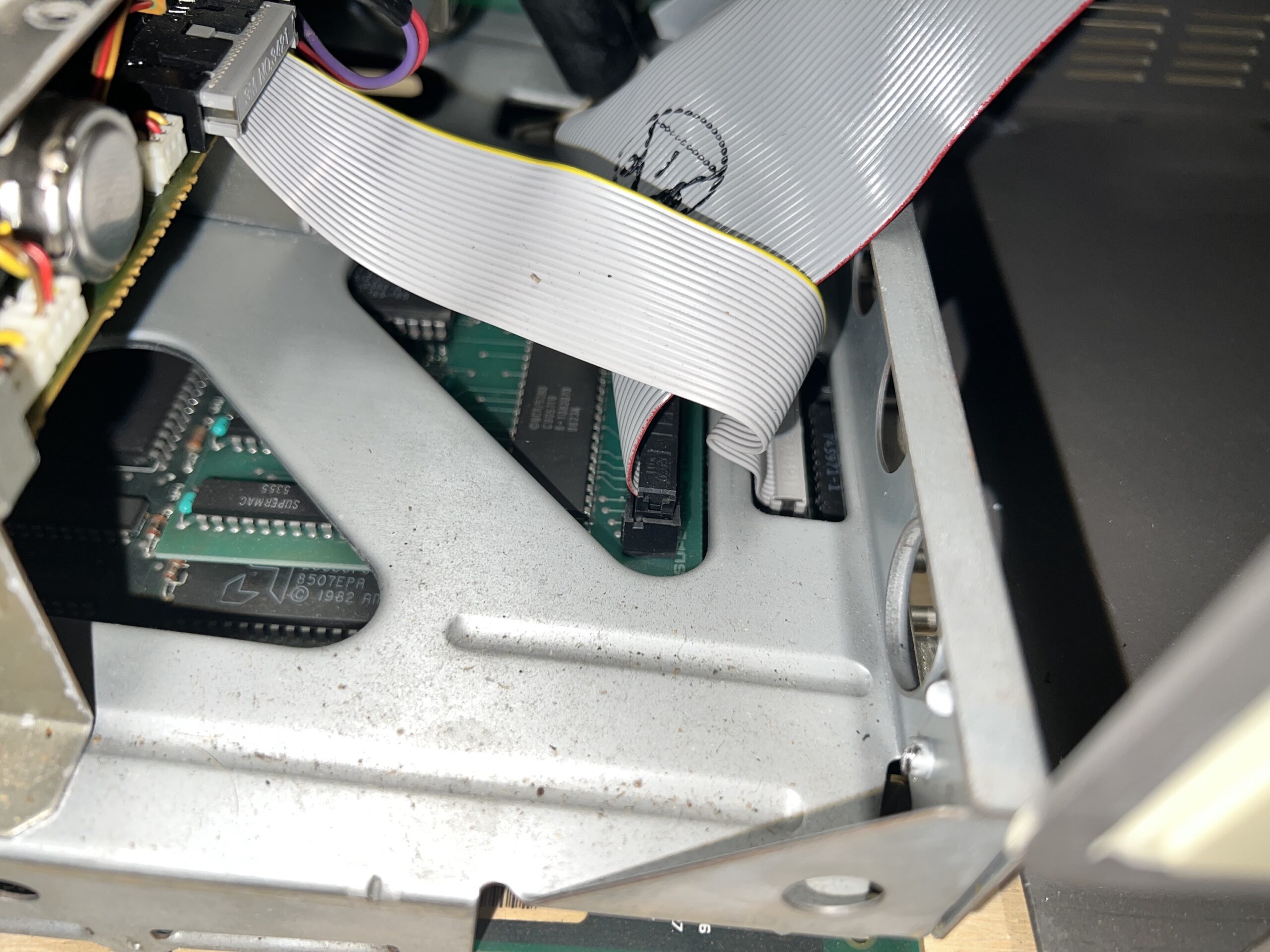
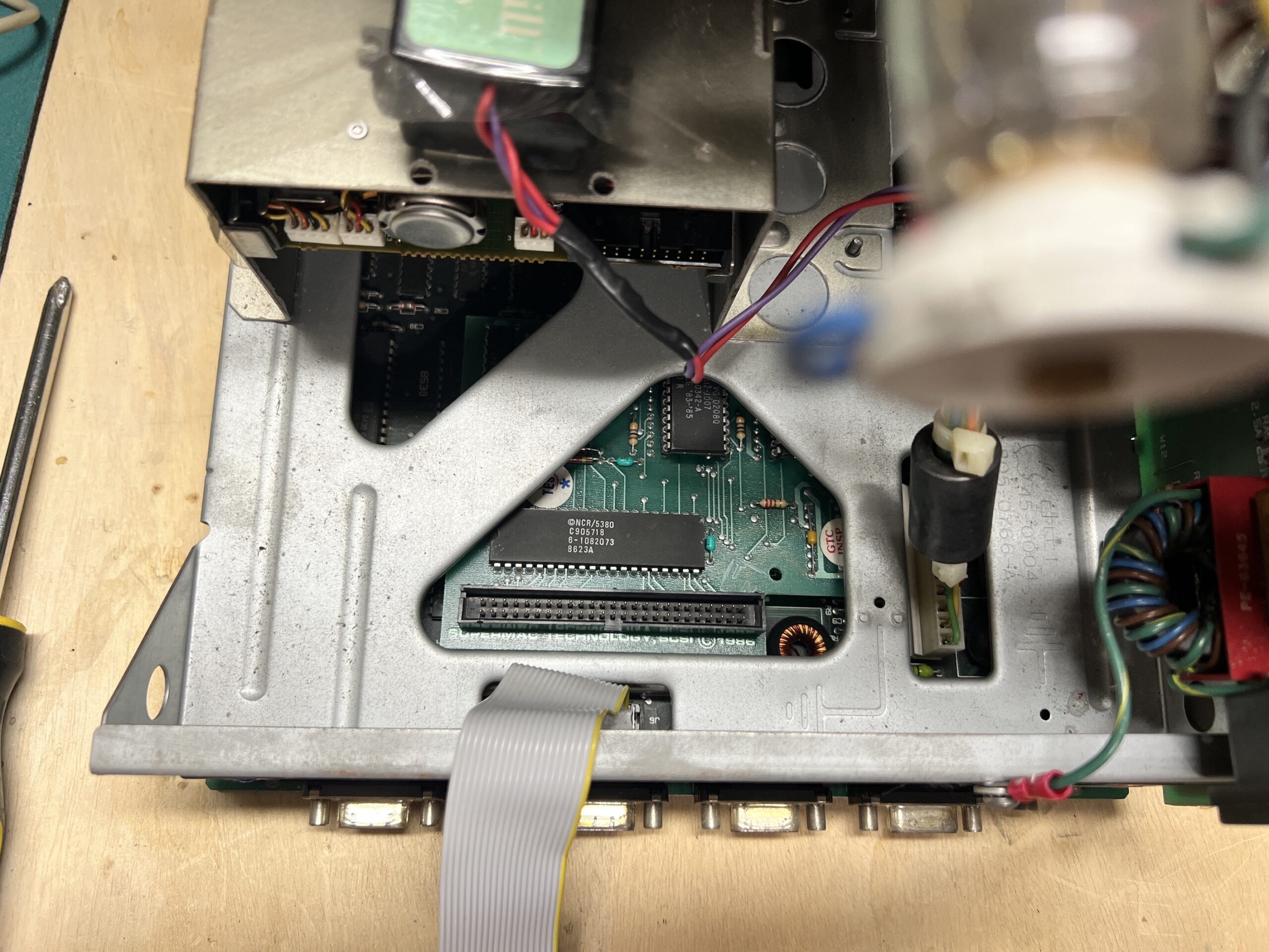

The SCSI add-on board is visible after disconnecting the floppy drive cable and 50 pin IDC internal SCSI cable. Although not this exact SCSI board, Pina’s Macintosh Repair and Upgrade Secrets page 196 illustrates this type of 3rd party addon.
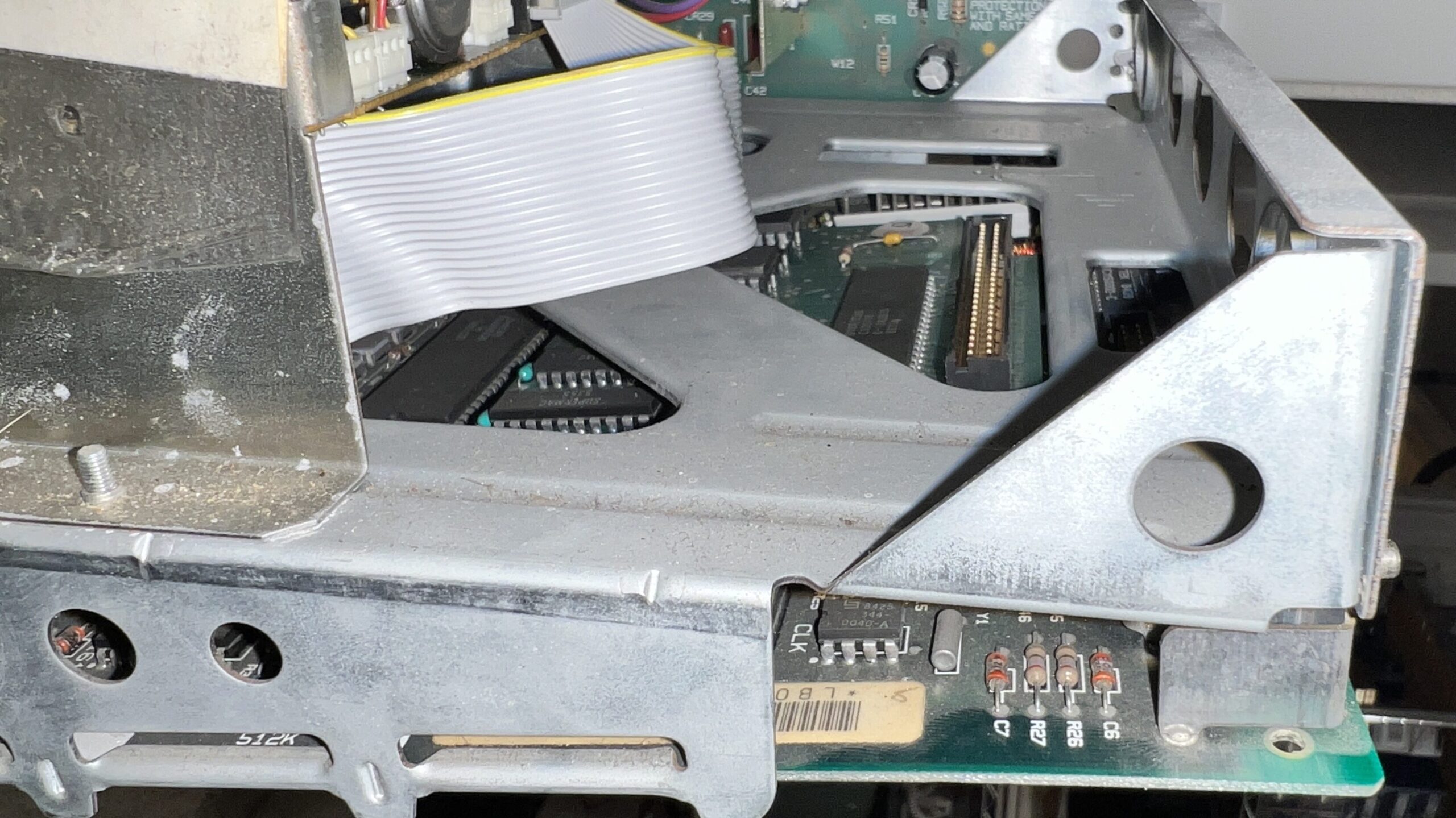
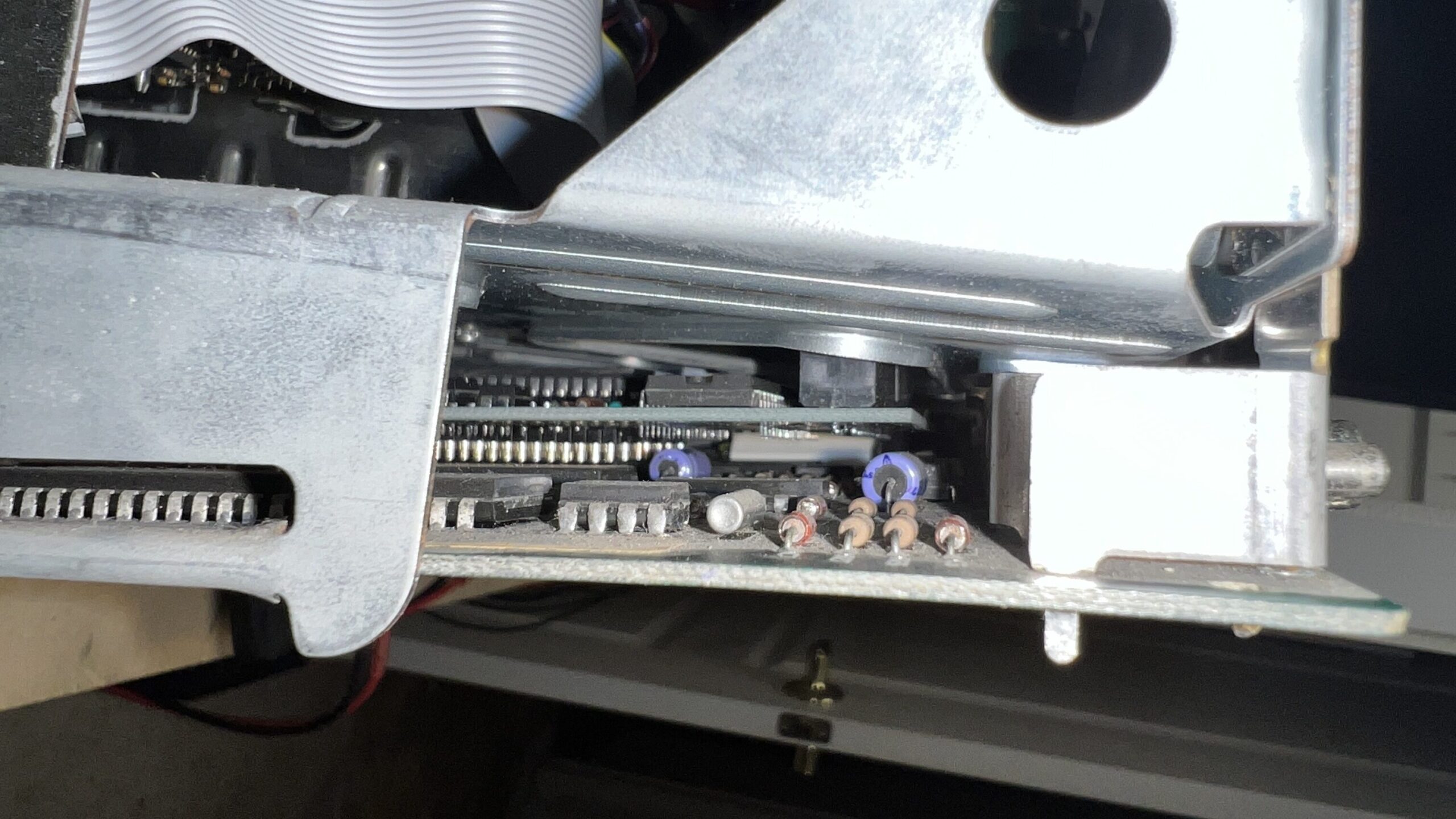
The logic board is supposed to slide out the back of the chassis, but that didn’t seem possible with the SCSI card attached to the it. The SCSI card plugs into the system’s ROM IC sockets. I removed the logic board by first popping the SCSI card loose, and carefully working the logic board out while being vigilant not to damage it or the SCSI card which was still trapped between the logic board and the chassis.

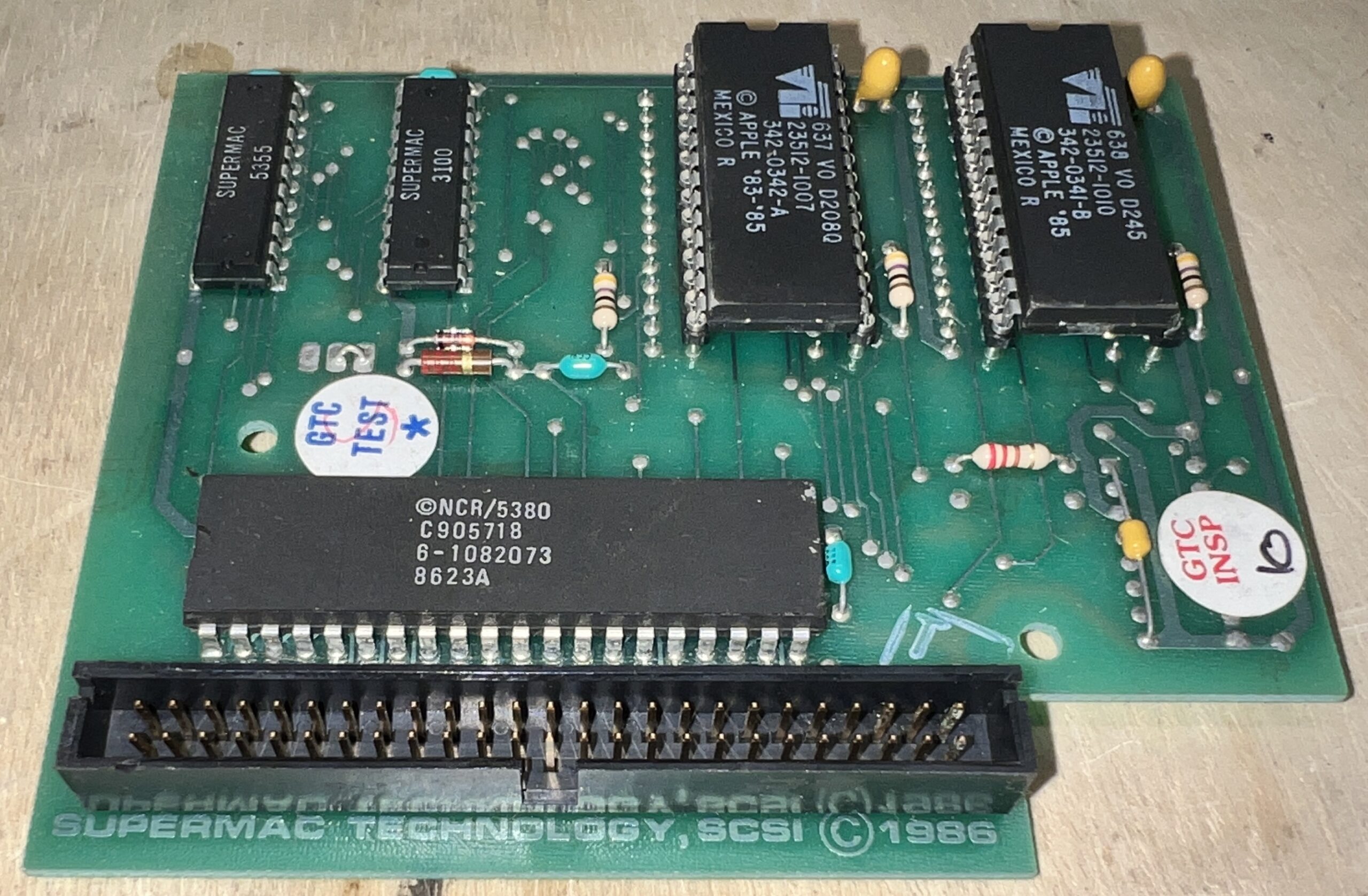
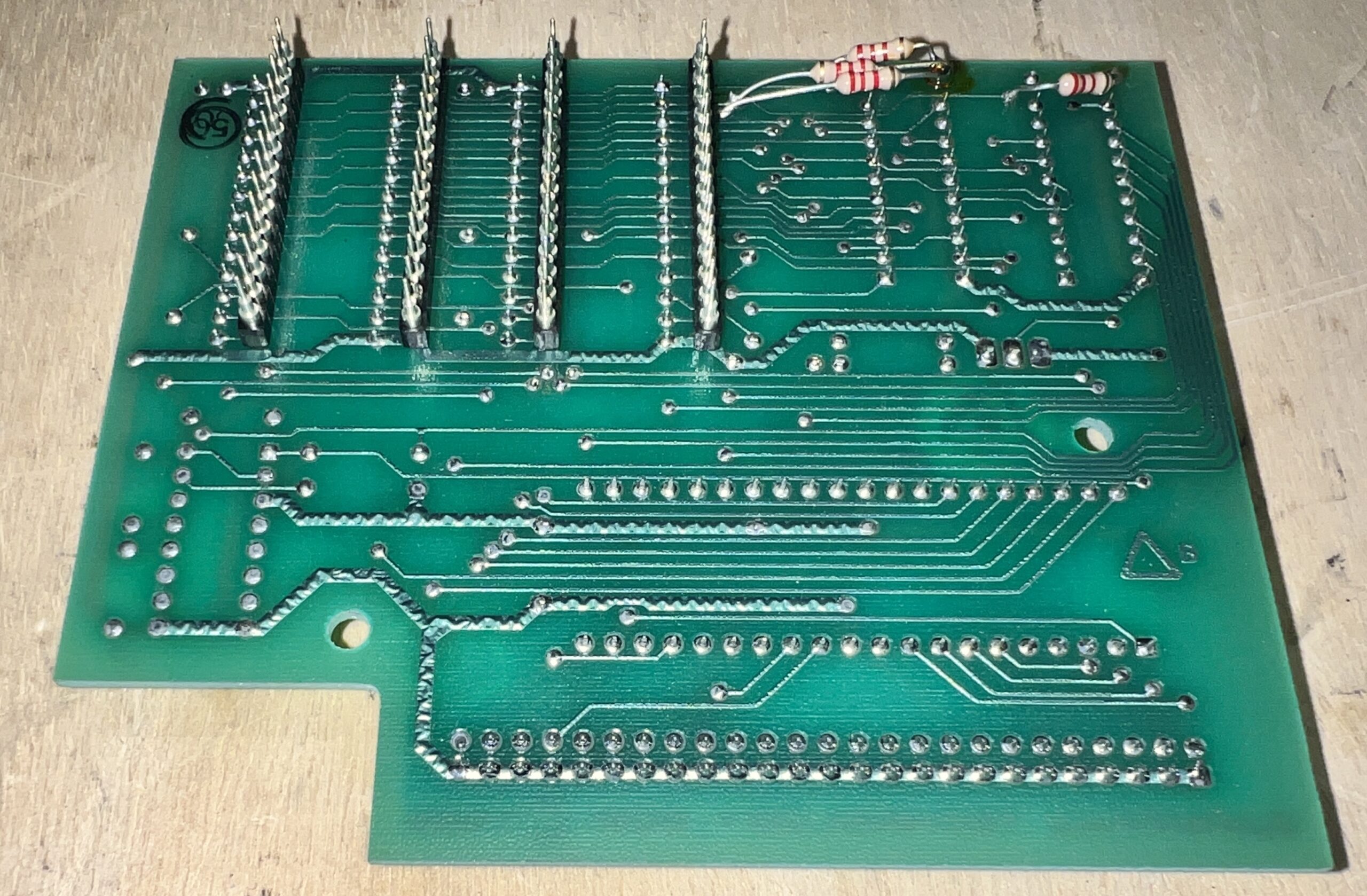
This SCSI card is a “Supermac Technology” SCSI card circa 1986. The system ROMs appear to be Mac Plus V2 ROMs according to this wiki (Internet Archive link here). These ROMs, with the addition of an 800K floppy drive (swapped in place of the original 400K it should have come with) would make this Macintosh 512K into a 512Ke, the ‘e’ meaning enhanced.

The logic board looked good, so I placed it, along with the SCSI card, back into the chassis which proved to be extraordinarily painful! It wasn’t easy getting the card to pop back into the ROM sockets once its all slid back into the bottom of the chassis. There is very little clearance, and the risk of bending the SCSI card’s pins was appreciable.
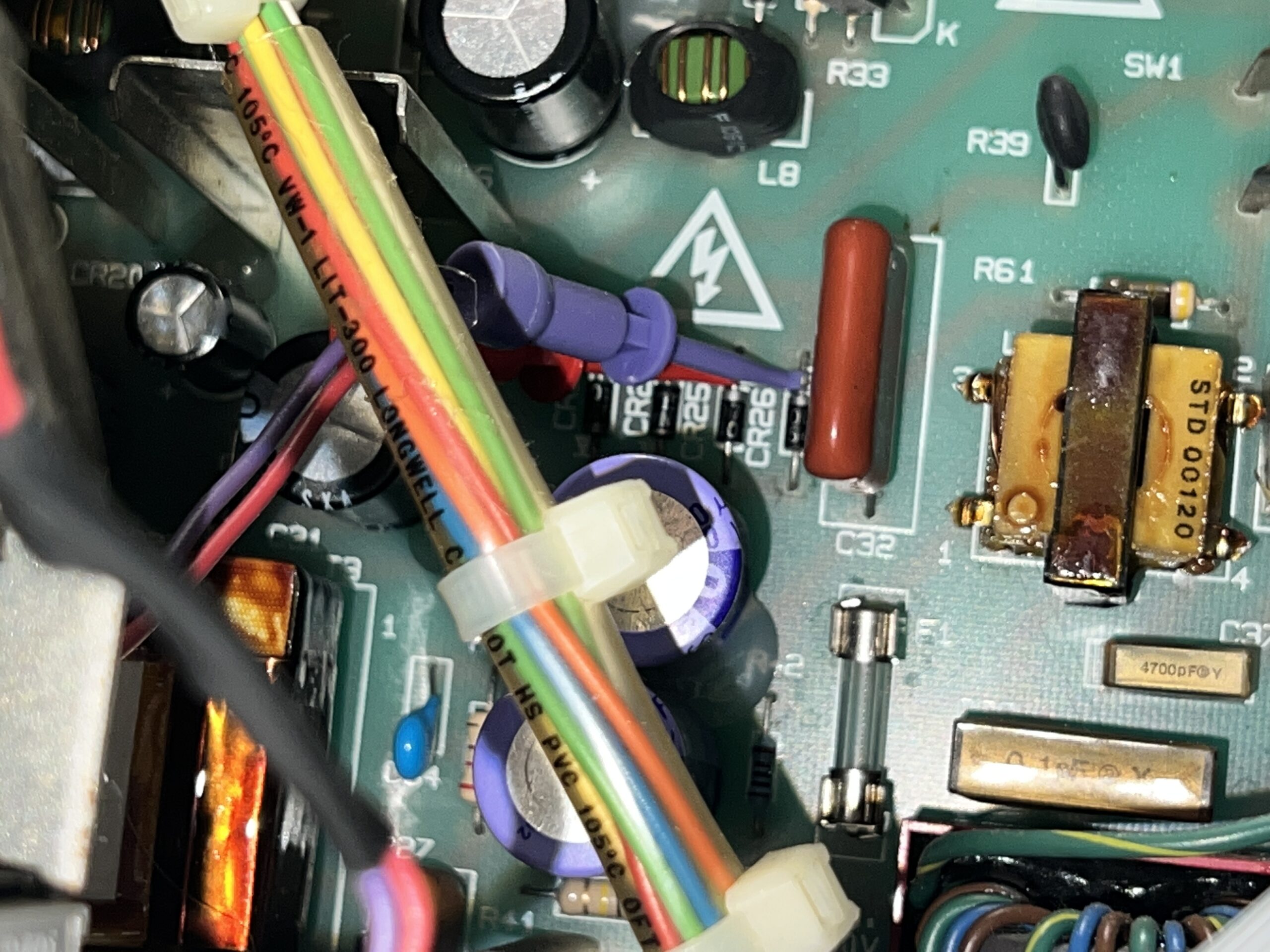
After giving the analog board a brief inspection, the only obvious parts pending failure were the RIFA filter capacitors. I went ahead and removed them before they could let the magic (stinky!) smoke out. Looks like if I had plugged this Mac in before removing them, they certainly would have let go.
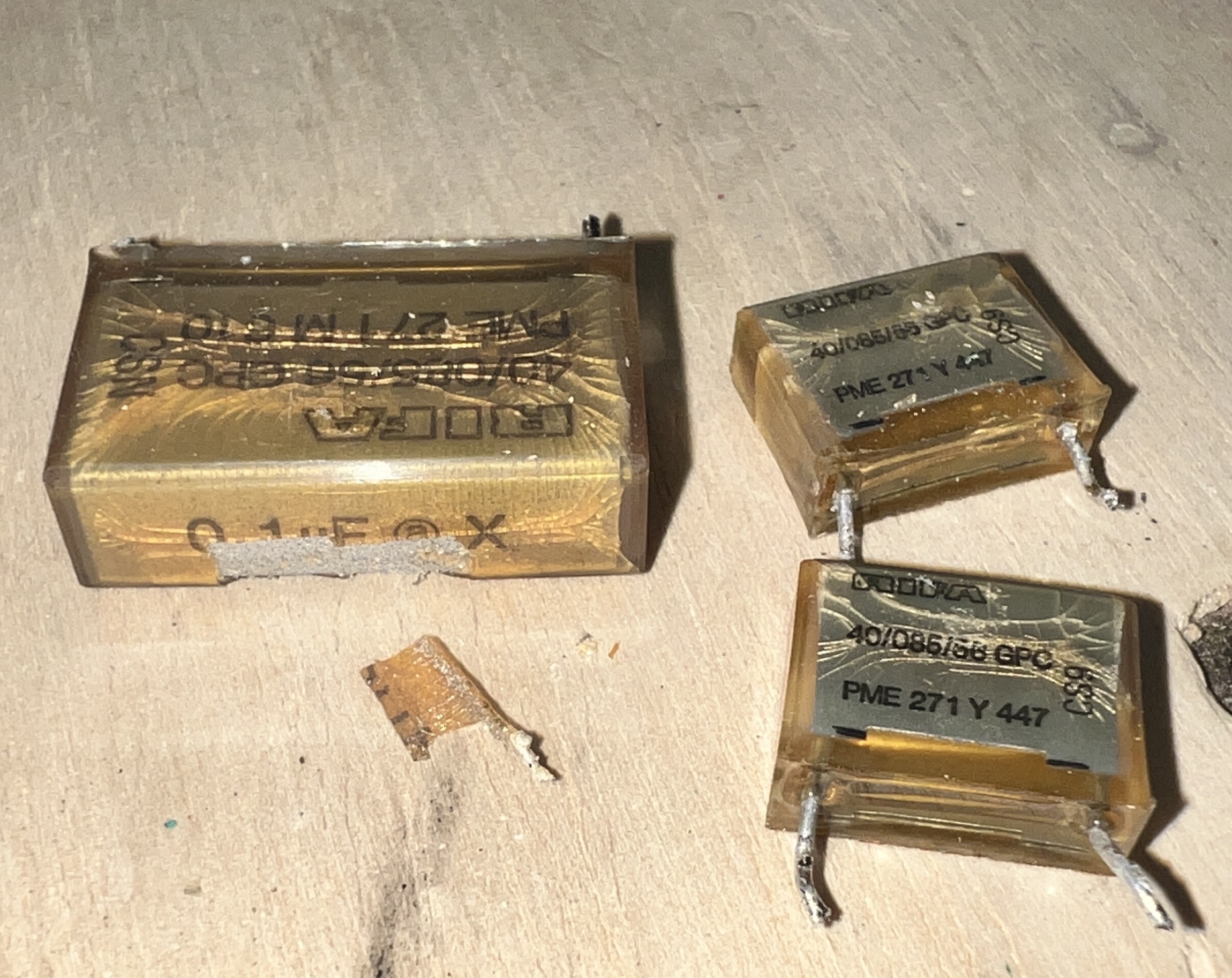
I knew I would eventually replace these RIFA caps with modern safety caps, but for now I thought it would be worth at least trying to power the Mac up. I uneventfully plugged the power cord in, then hit the power switch.
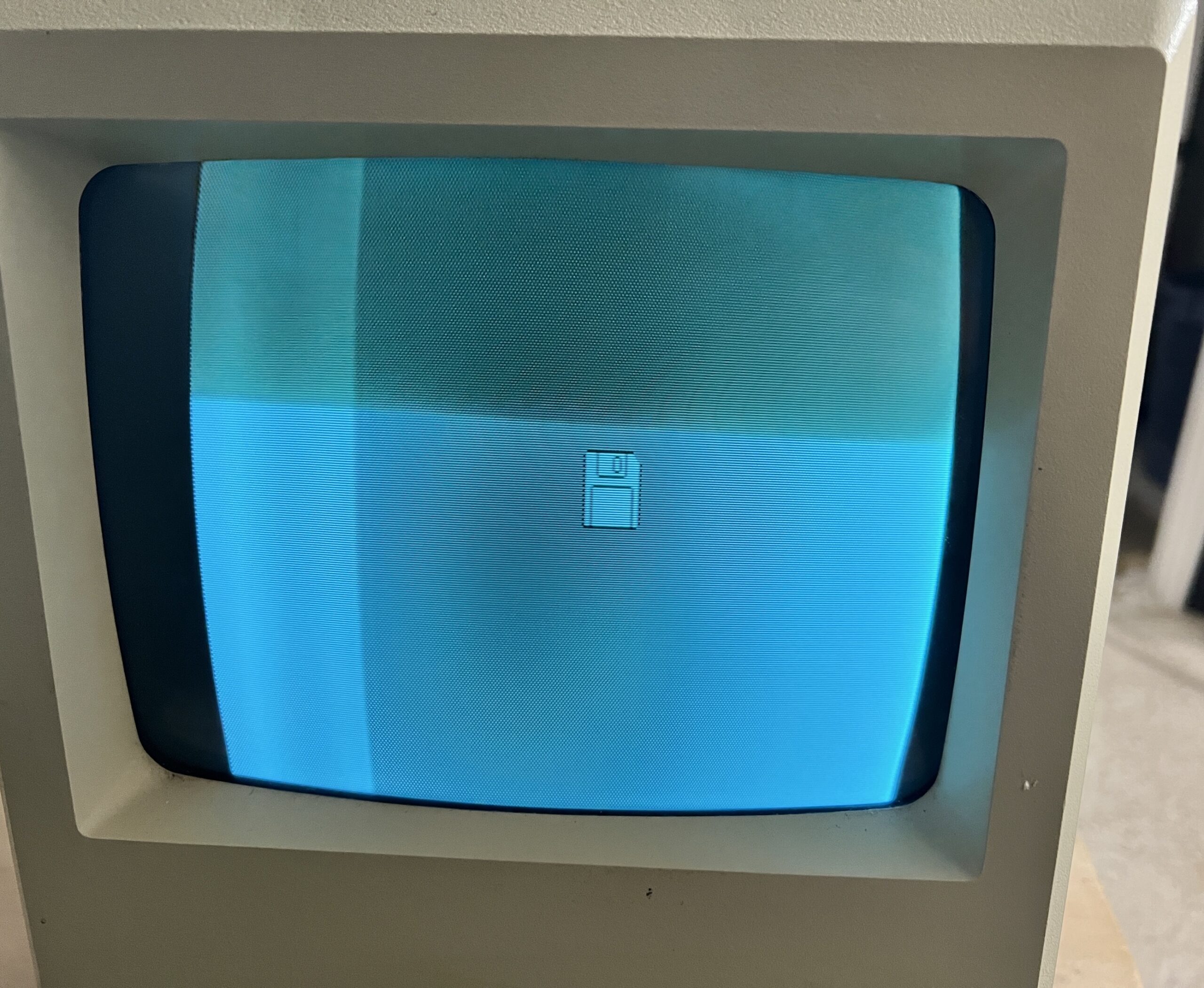
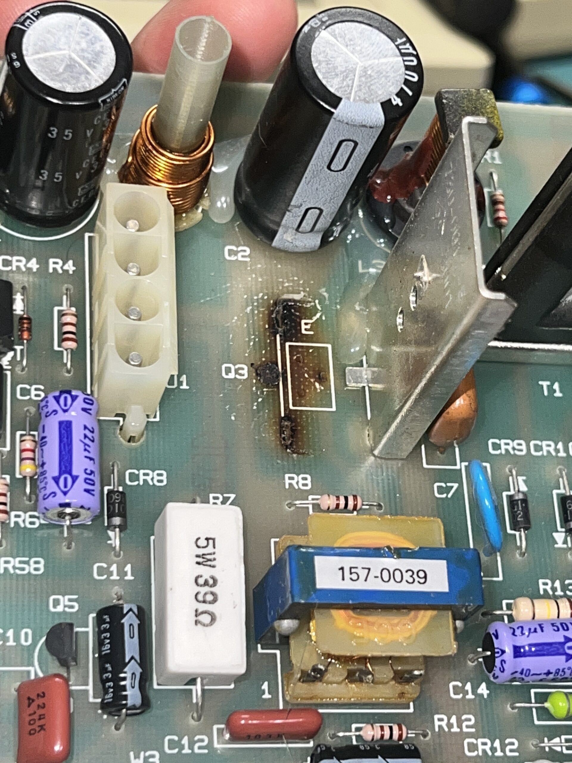
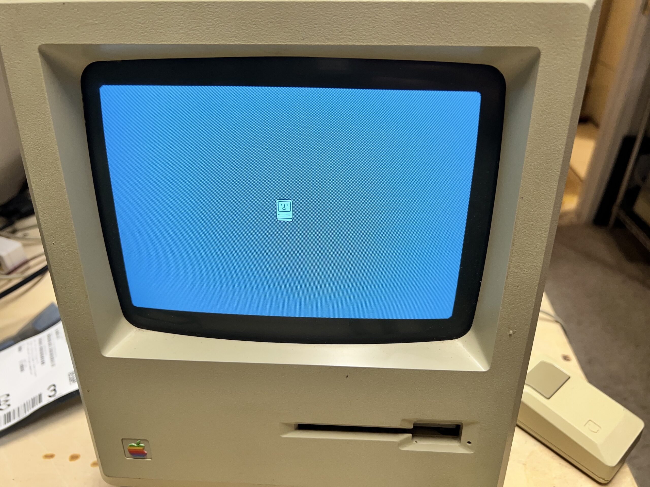
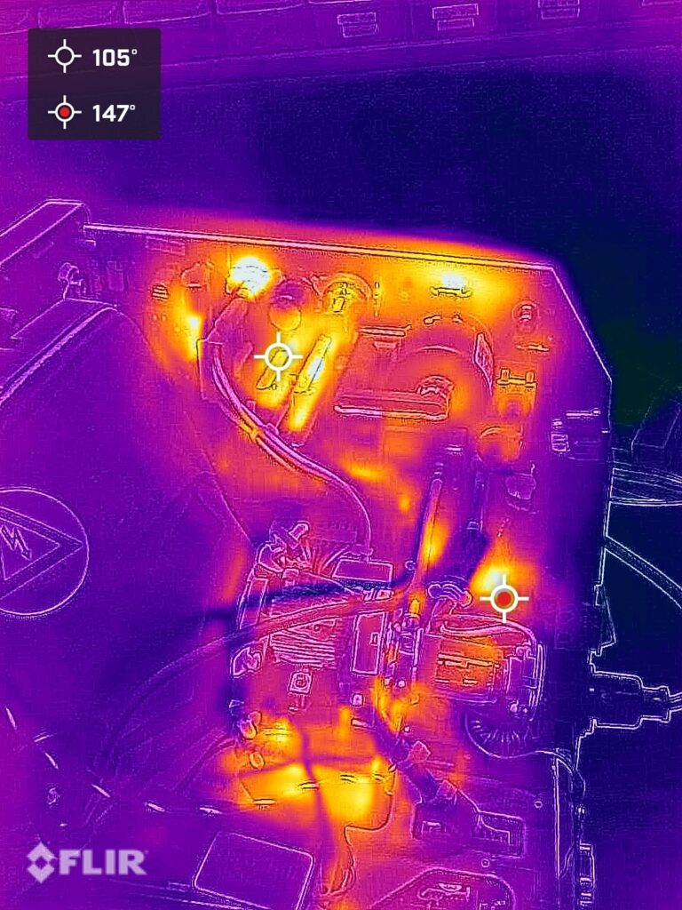
I was greeted with a much anticipated BONG from the system speaker as it successfully booted and awaited a startup disk. The picture definitely didn’t seem healthy on the screen. As seen in the image, the picture was vertically elongated, shifted slightly to the right, and had a strange vertical bar on the left side of the screen. It was also slowly getting darker, and it generated such a strong sent of hot metal, I thought perhaps I’d left my soldering iron on! Out of caution, I switched the power off to locate the source of the heat.

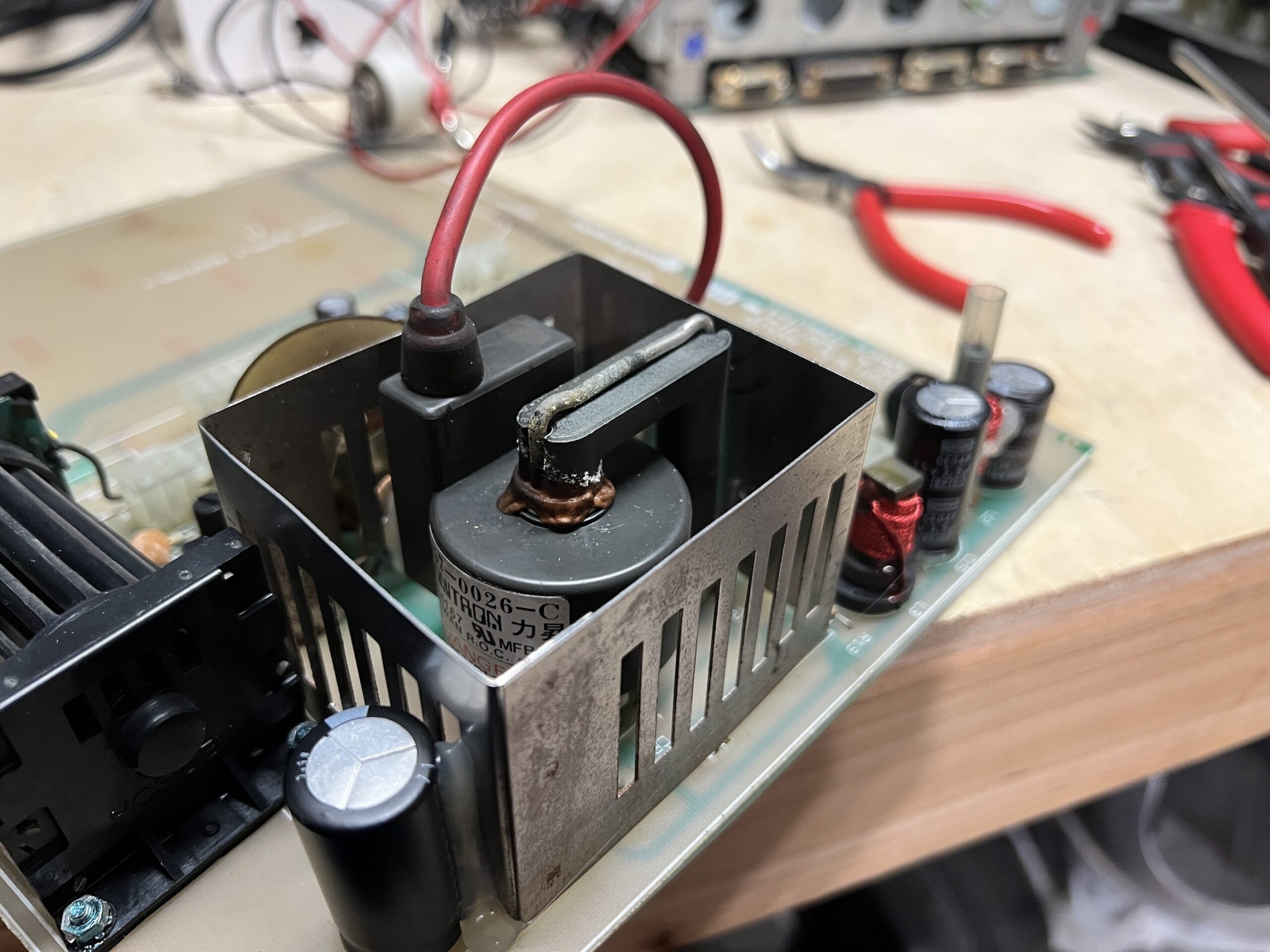
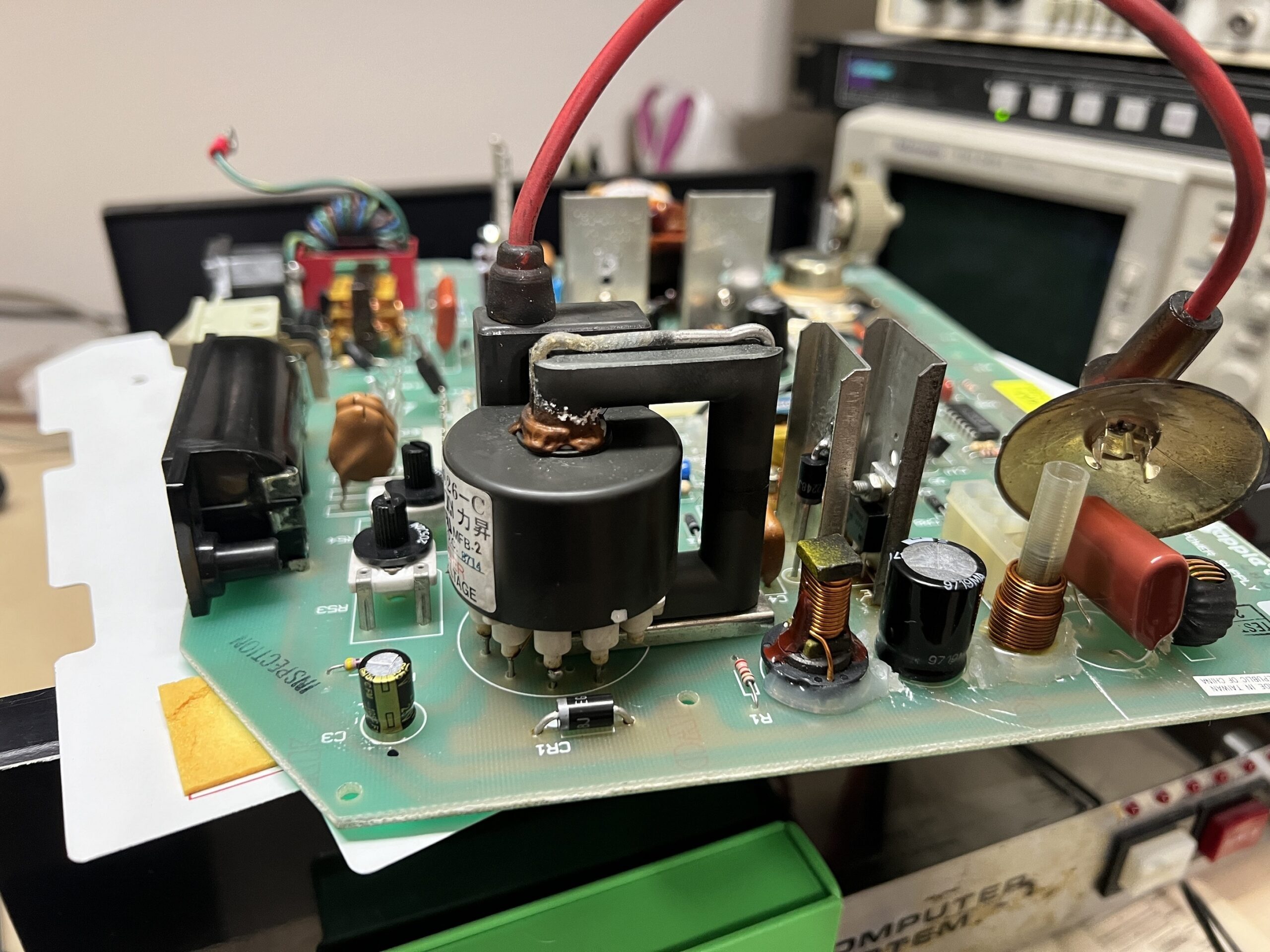
It wasn’t hard to locate the toasty horizontal output transistor (aka HOT; no pun intended!). Following the information in Pina’s Macintosh Repair and Upgrade Secrets, it’s noted that screen fading or darkening points to replacement of the HOT (Q3) as well as T1, the flyback transformer. I couldn’t find any reasonably priced replacement flybacks online, so I wanted to be absolutely certain that my flyback was in need of replacement by testing it first.
Rather than purchasing a proper flyback tester, my curiosity led me to search for information regarding how flyback transformer testing works. I found some useful info online and used that information to build a test jig.
To first check for an open winding, I used a multimeter to look for continuity between each terminal of the transformer windings. I used schematics and the circuit description for the analog board found here (Internet Archive link).
Another type of fault for which to test is a turn-to-turn short. One method to identify this failure mode is a ring test. The ring test takes advantage of an oscillation that occurs between the high Q flyback transformer windings and a non-polarized capacitor placed in parallel when an impulse is applied to the circuit. A healthy winding (no turn-to-turn shorts) will transfer the energy back and forth between the capacitor and the inductive windings a good number of times before it decays. A winding with a short will present a waveform that appears critically damped and oscillate only a small amount or not at all.
The assembly manual for a commercially available tester (Internet Archive link) called the K7205 has a good diagram of the expected waveforms from the ring test. Here it is borrowed from the linked PDF:

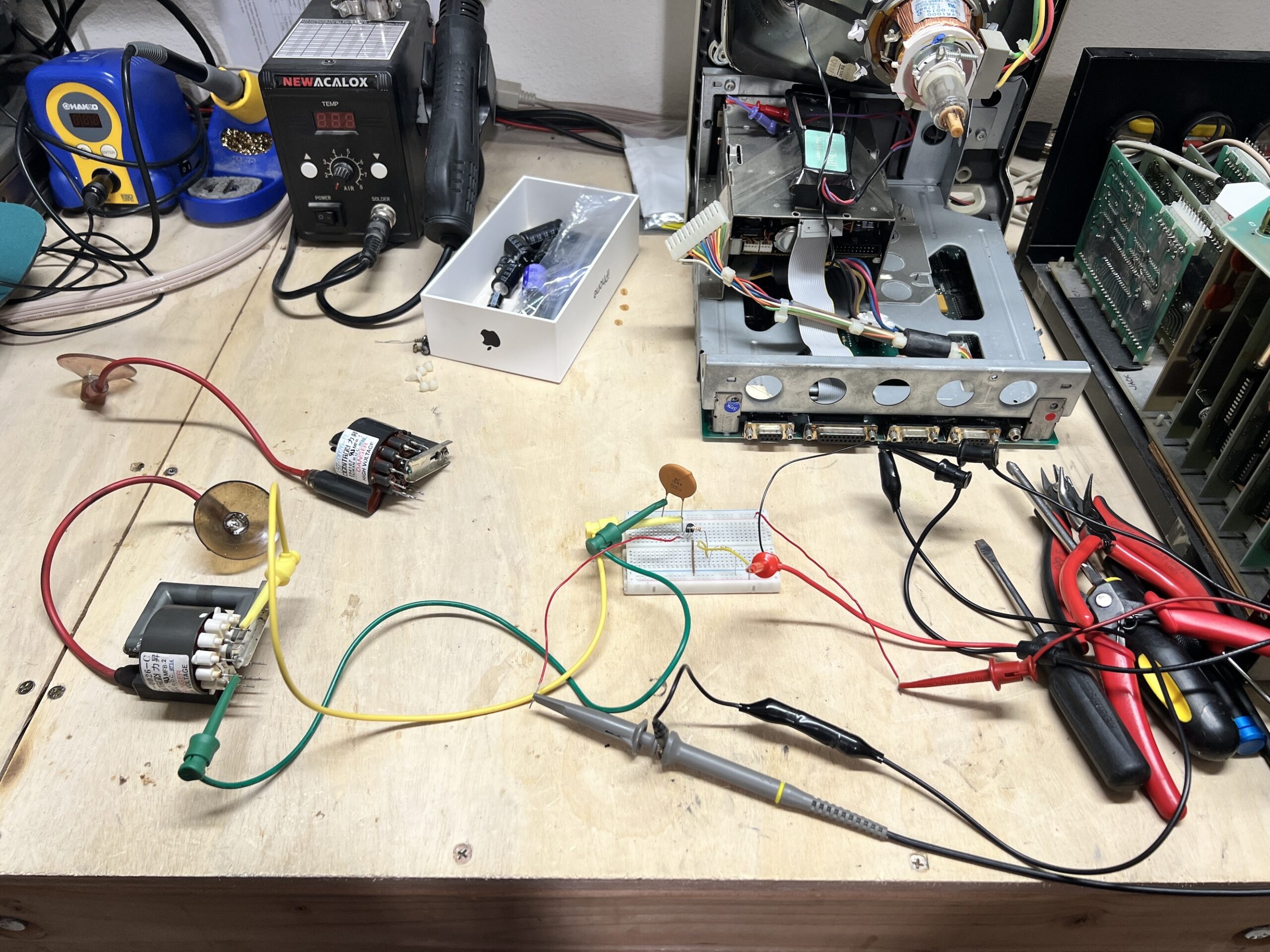
This document (Internet Archive link) was probably the most useful in putting together a test jig. Simply utilizing some type of pulse generator to create a clean impulse (and not a switch which would “bounce”), a non-polar capacitor of appropriate size (I had to guess and check), and an oscilloscope to view the ringing oscillation waveform is sufficient.
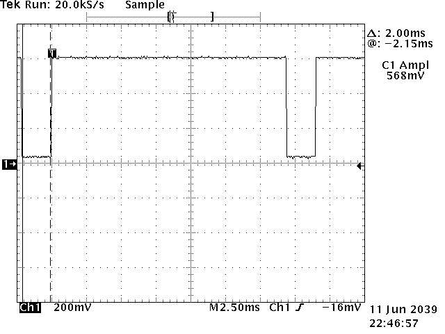
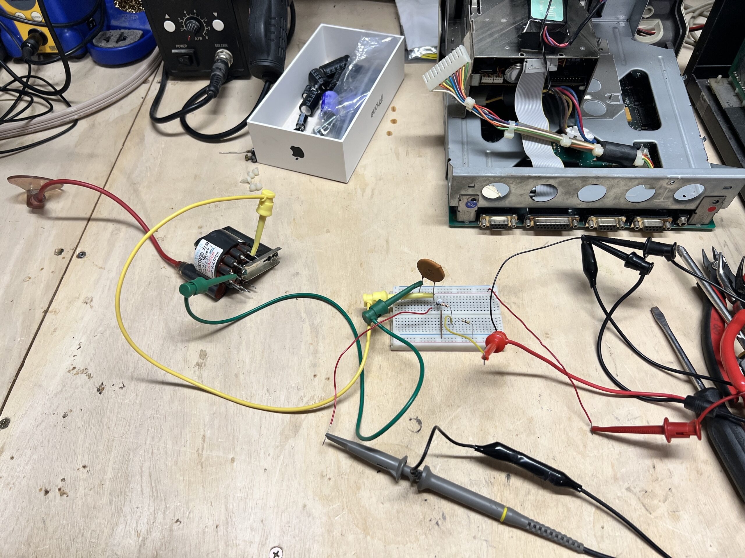
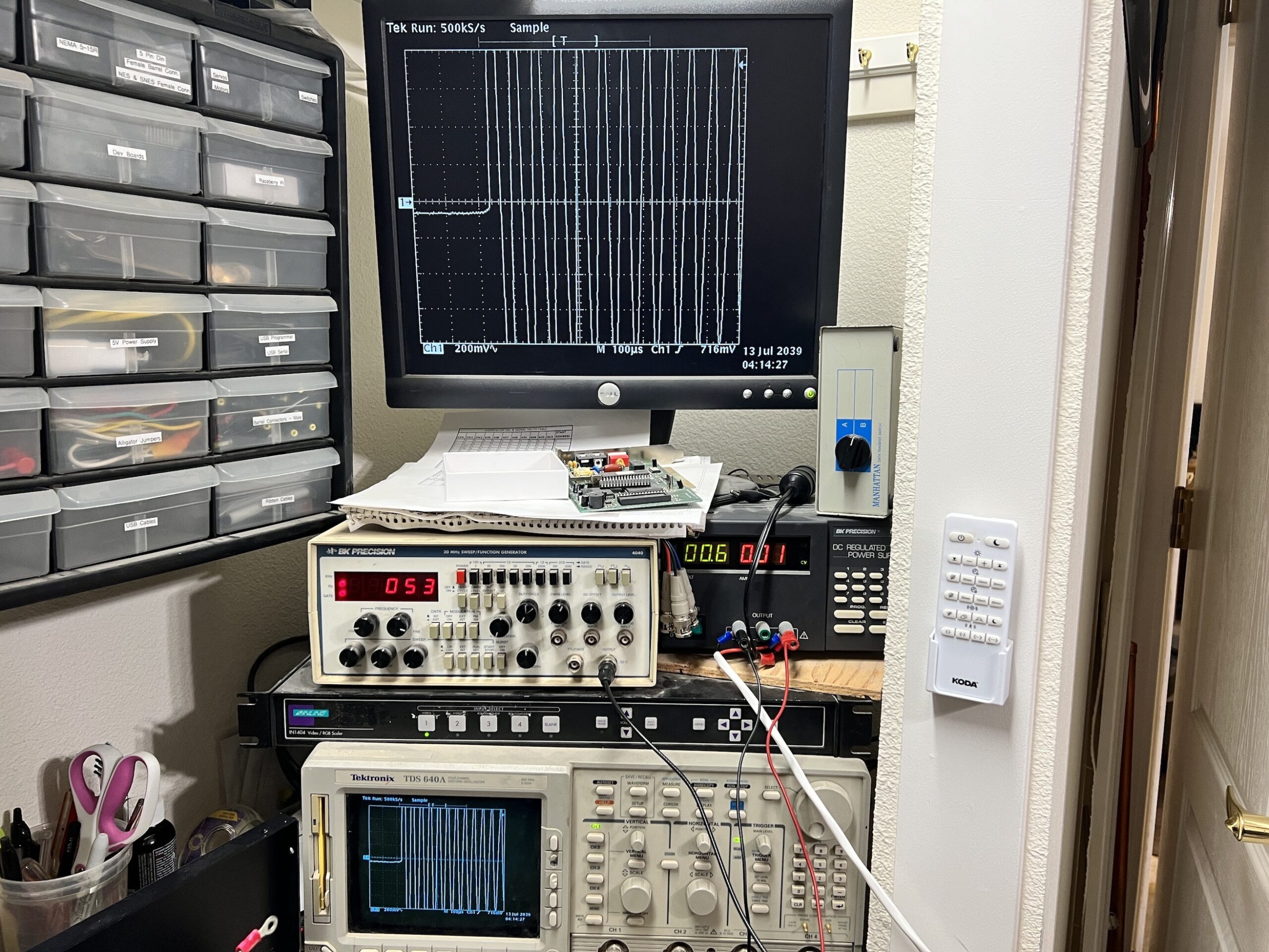
I wasn’t entirely sure what the output current rating of my function generator was (which I used as the source for the impulse), so out of caution I decided to use the function generator to turn on a transistor which switches the voltage from my bench power supply to act as the impulse for the test. Here’s what I put together for a quick and dirty test jig and a snapshot of the output pulse of the circuit. This snapshot was made without the capacitor and flyback connected to the circuit, and a resistor was added in place of them. This was done to measure the circuit’s output waveform for on-the-fly adjustment of the function generator as needed to create the desired pulse. Notice the output is normally high and is pulsed low. This is because the flyback and capacitor will be normally connected to positive supply voltage, and the common emitter transistor circuit switches ground to the flyback and capacitor. I have the circuit working at 500-600 mV utilizing a 2 ms pulse.
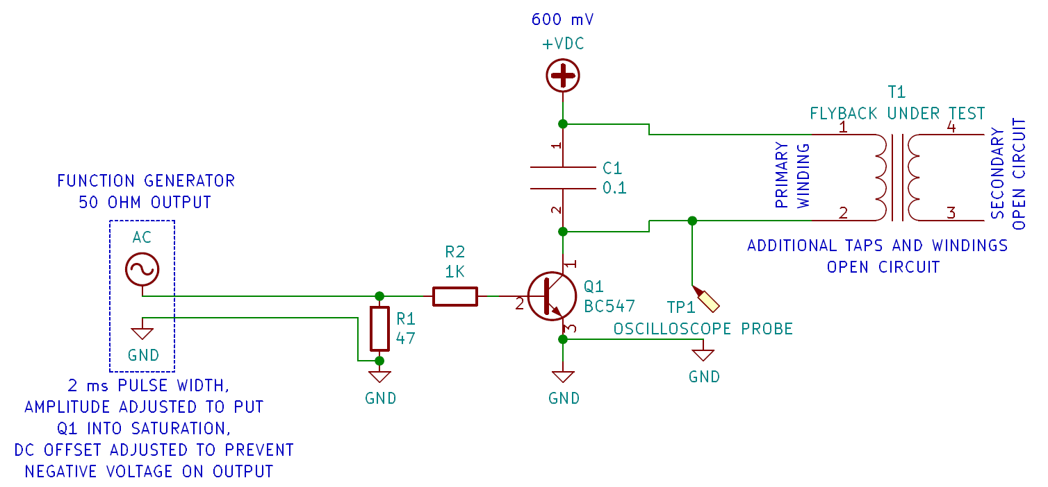
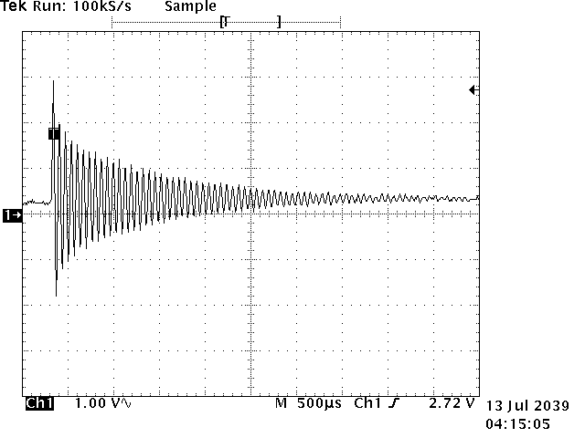
Here’s how it was hooked up and the resulting waveform:
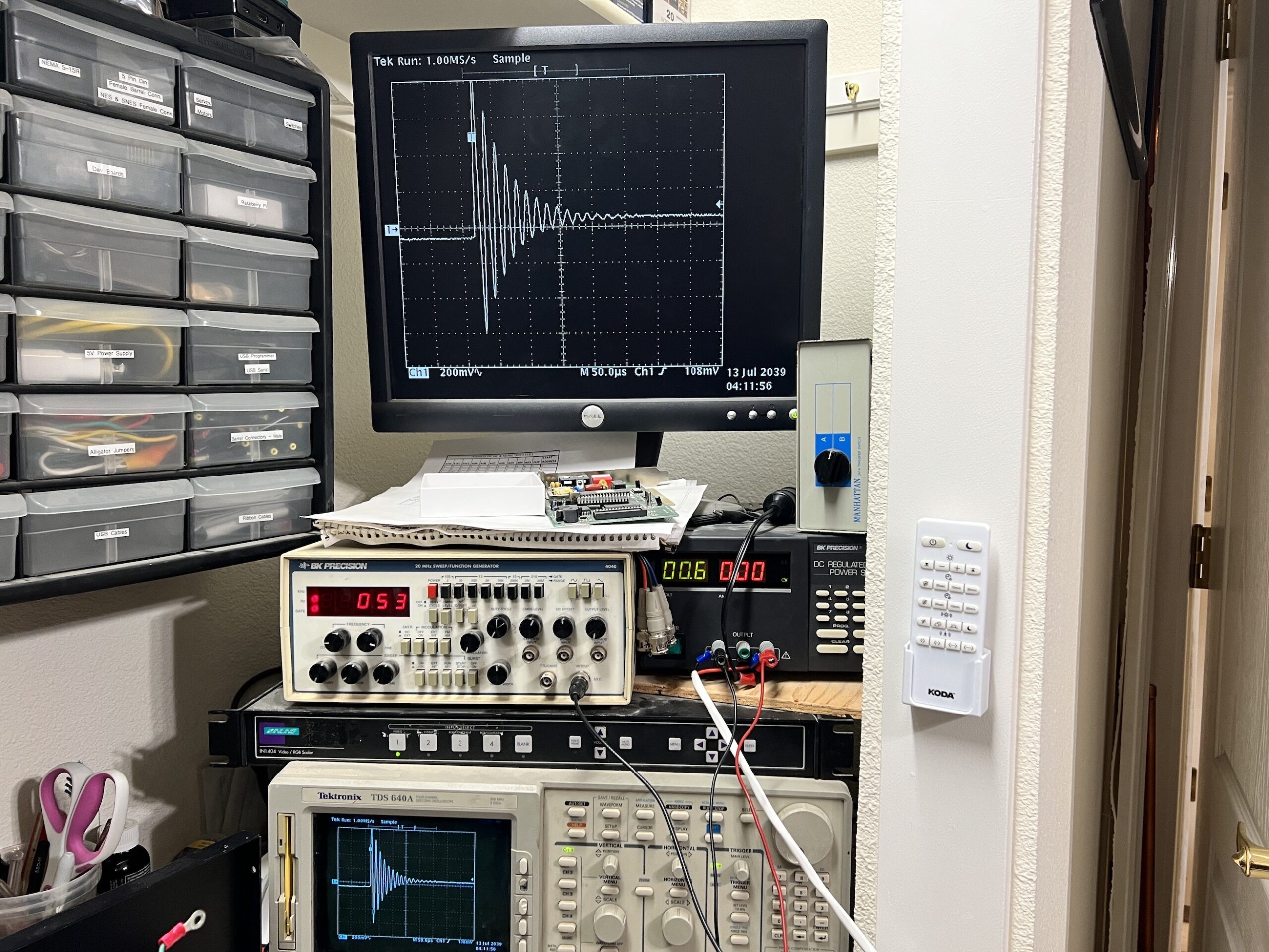
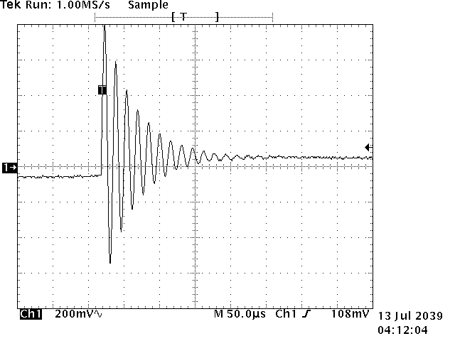
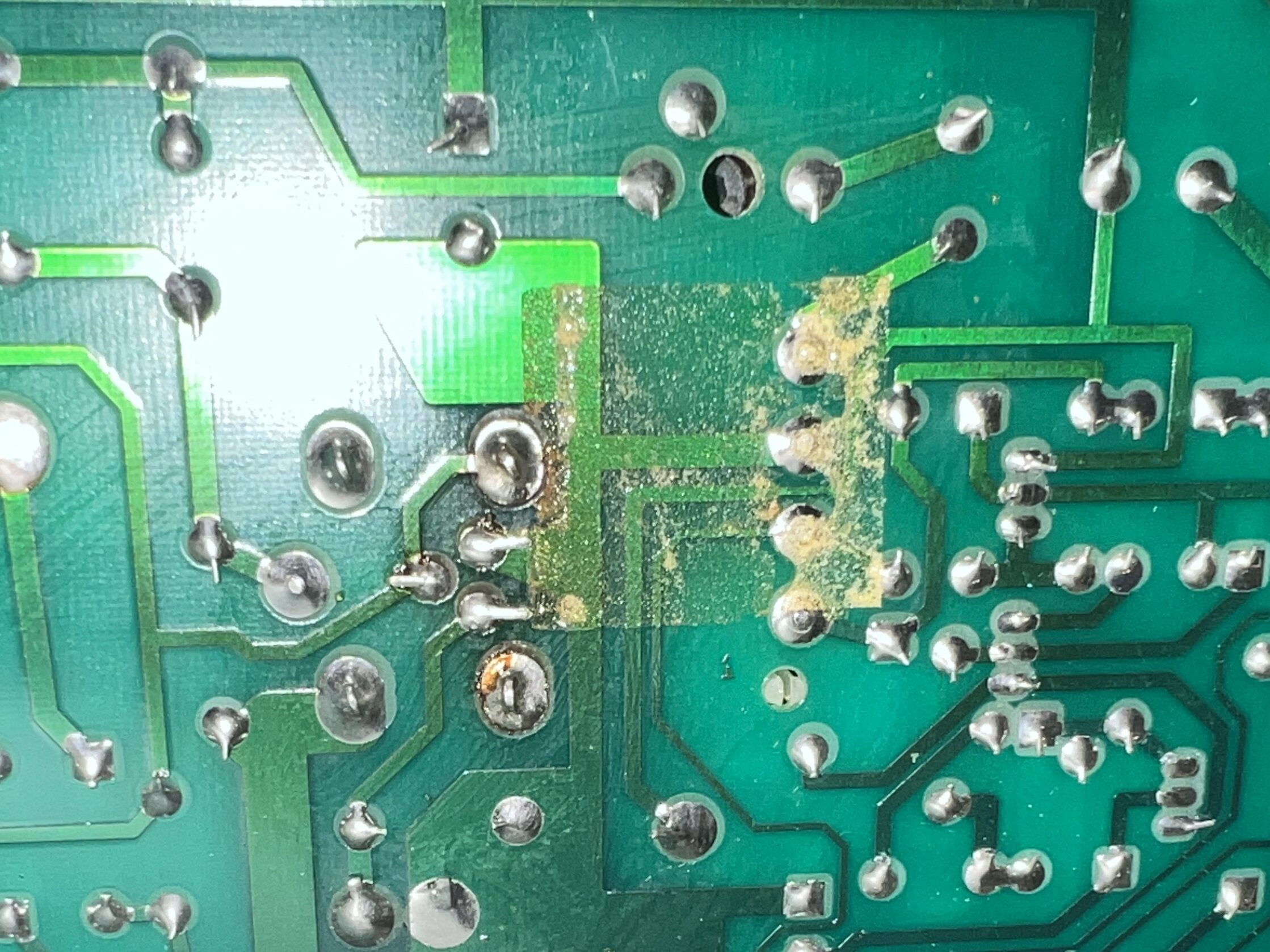
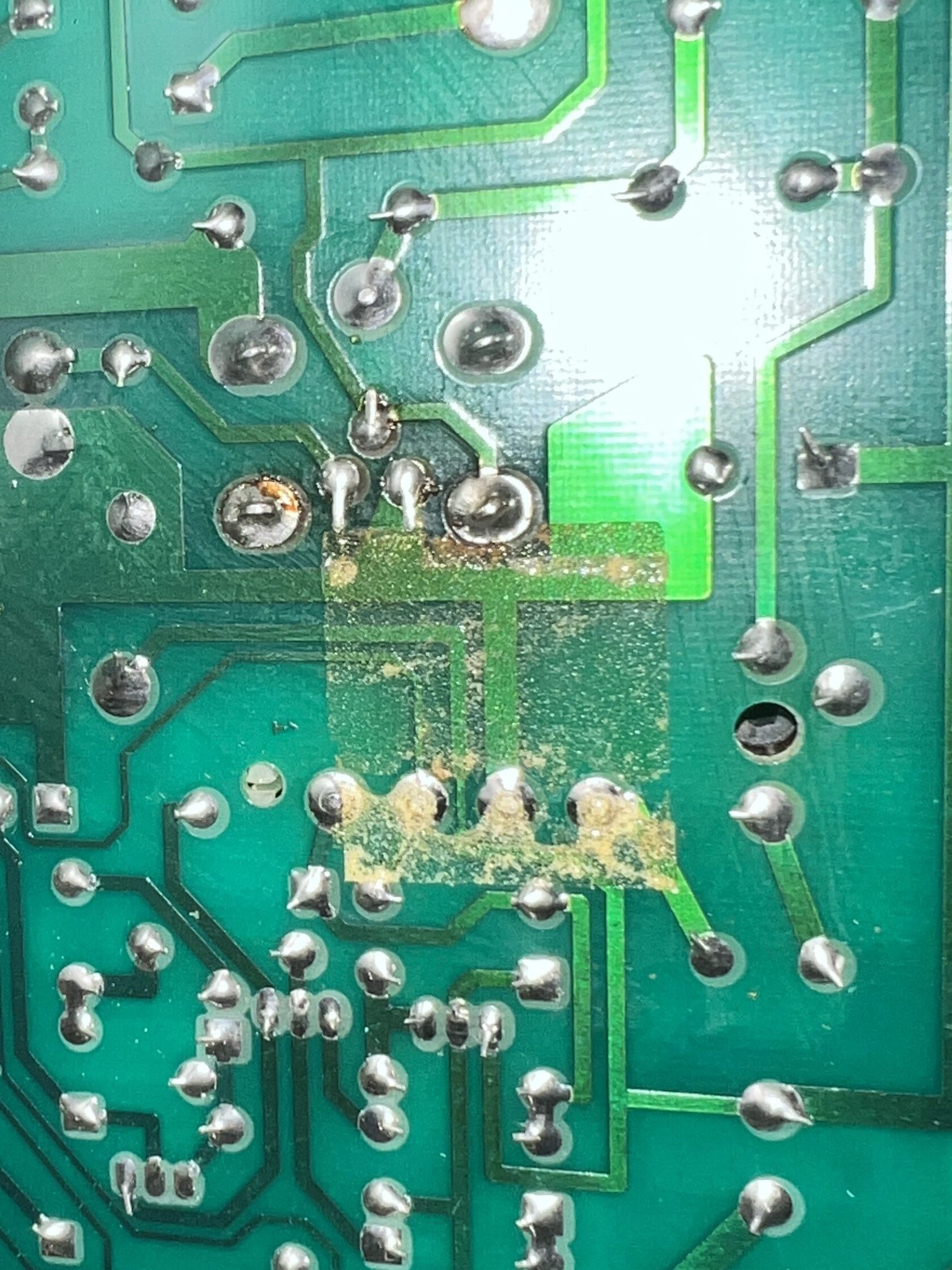
The waveform seemed to match better to the above example of a good flyback transformer rather than a bad one. Believing perhaps the flyback wasn’t the issue, I purchased a handful of HOTs to replace the failed one along with a capacitor kit and the other recommended components to upgrade the analog board outlined in Pina’s Macintosh Repair and Upgrade Secrets. While I was replacing components, I reflowed the solder joints for all connectors on the analog board. Some joints were definitely in need of it!
After powering on the system with a fresh HOT, unfortunately the result was the same. This burned up the freshly installed HOT. At this point I made a decision that I wanted to avoid: buying a donor board to harvest its flyback transformer.
I picked up a later model Macintosh analog board for the job.
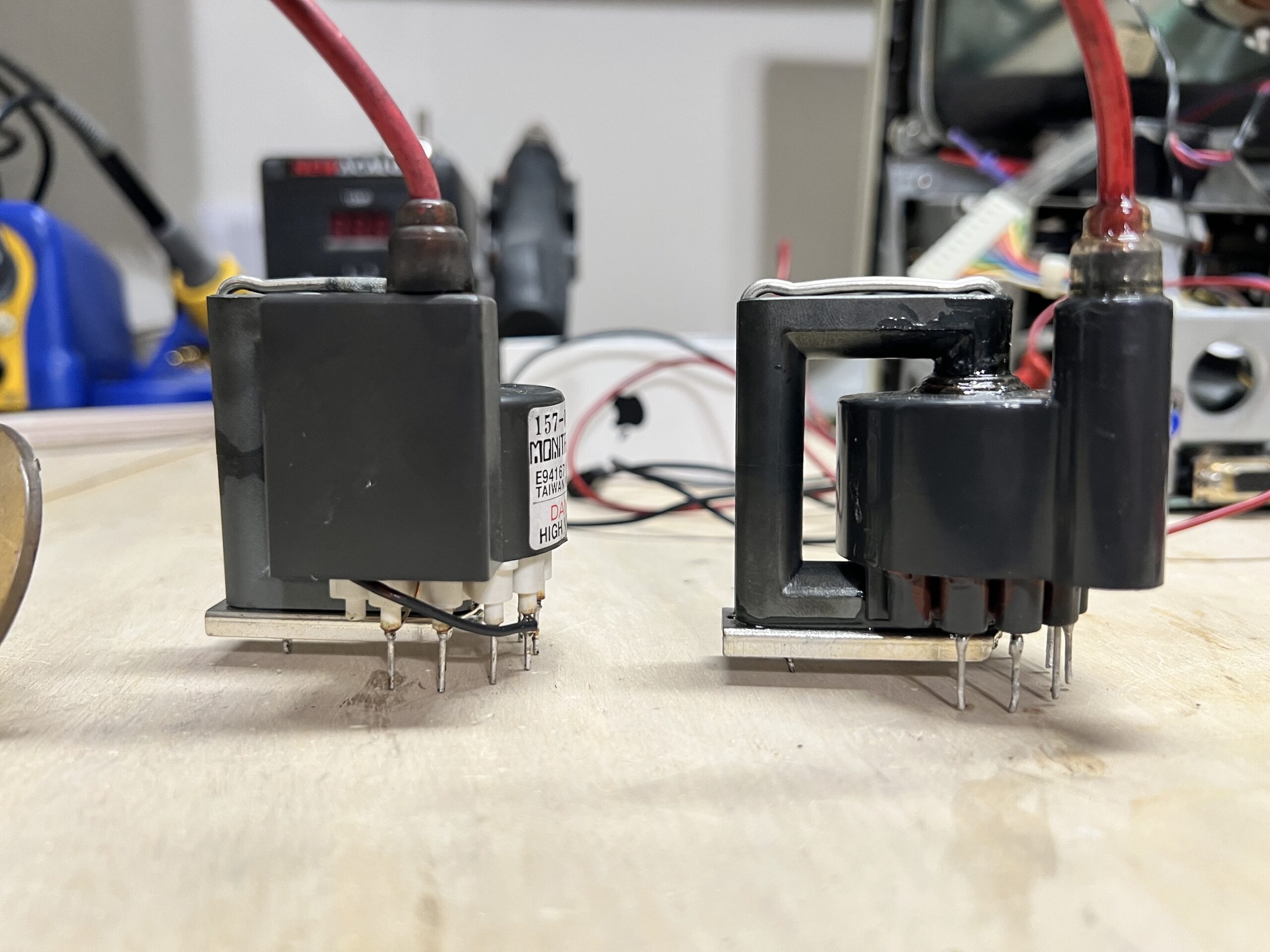
You can see the old and new flybacks are slightly different. The donor one has a -C suffix, which is thought to be a better flyback according to Pina’s Macintosh Repair and Upgrade Secrets. The donor flyback is UL approved, physically larger (better heat dissipation), and a bleeder type. Bleeder type flyback transformers include an internal bleed resistor to discharge the CRT after power off.

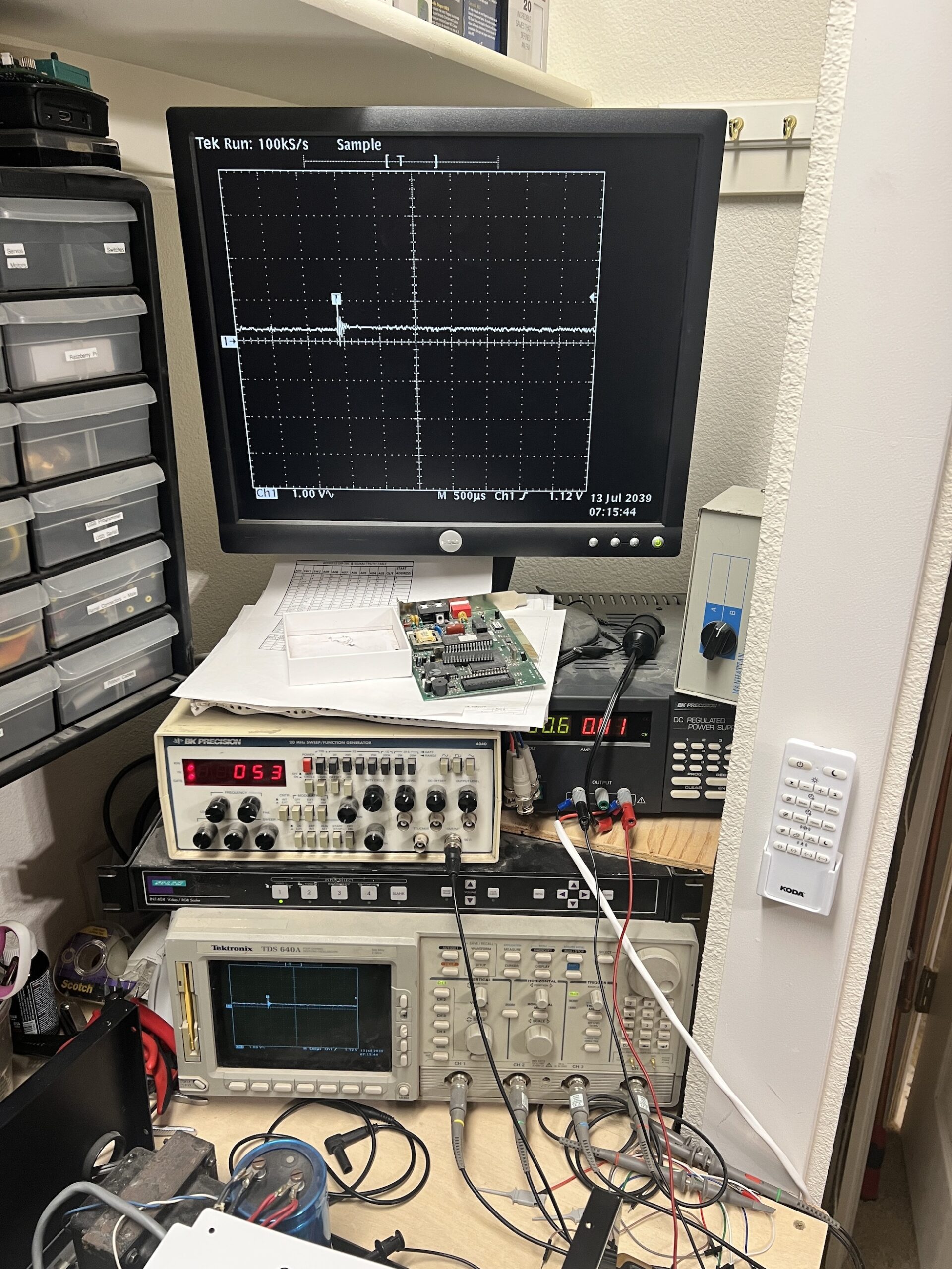
Before installing the donor flyback, I wanted to put it through the exact same test to determine if my test jig was totally useless. The pictured screen shows how the waveform looked without changing the vertical scaling and only slightly adjusting the horizontal scaling from the previous flyback’s test. There was a great difference!
After adjusting the scaling, it looks like a very good oscillation:
That made me wonder what the old flyback’s waveform would look like with this scaling, so I tried it out:
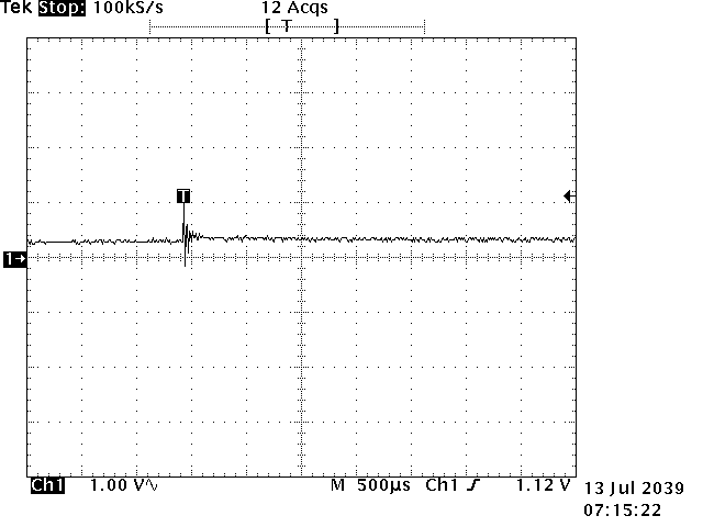
Pathetic! This old flyback must definitely have a short!
Satisfied seeing a difference in the performance of the flyback transformers under test conditions, it was time to put the donor flyback into the analog board (along with another new HOT) and test it out.
Throughout flyback testing, I noticed the donor flyback’s epoxy was flaky and losing its seal just as the original flyback’s had been. As a precautionary measure, before reassembly I used Super Corona Dope from MG Chemicals to coat over the epoxy on the donor flyback, letting it run inside the flyback to help reinforce the insulation in the center of it. I also applied some along the insulation of the high voltage lead as it entered the top of the flyback.
After powering it on, there was a good, stable screen, and the new HOT didn’t get hot!

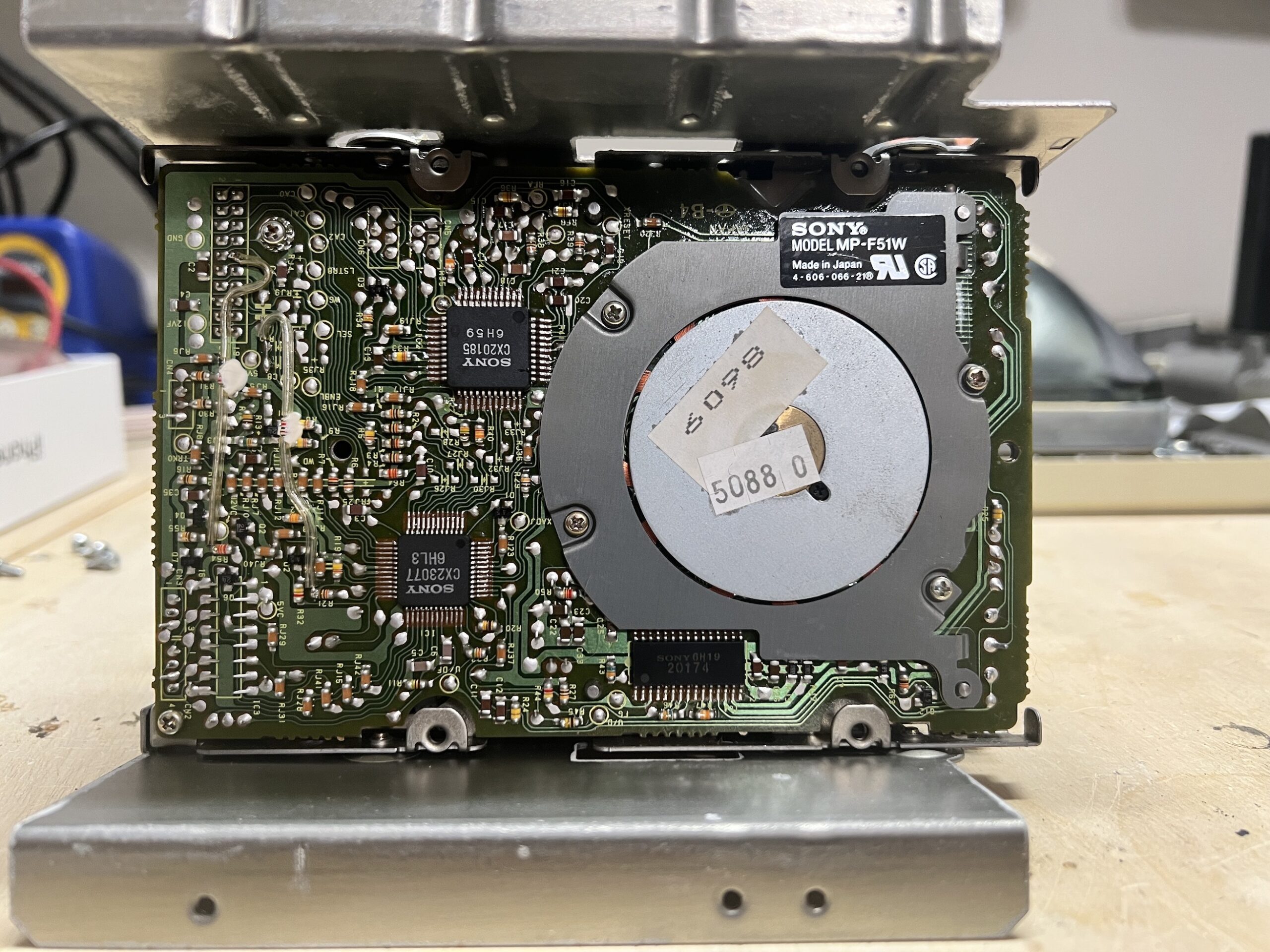
Surprisingly, it spit out the boot disk. I say surprisingly because often the eject gear is broken for these old Macs. I pulled the drive out to clean and lubricate it to find that it had indeed been swapped to an 800K drive!

After servicing the drive, the system still wouldn’t boot. I found the boot disks included from the previous owner were bad. Running a Greaseweazle connected to a 3.5″ PC floppy drive from the Fluxengine software on my modern PC, I was able to create a new boot disk. Now the system works great!
To test out the SCSI board, I connected a BlueSCSI SD hard drive emulator. It worked great on USB power, but I really wanted the BlueSCSI to obtain its power from the SCSI termination power signal on the SCSI connector. I found that this SCSI board didn’t have termination power connected to the pin on the SCSI connector, so I added a diode connection to it just as the mod is done to add it for a Macintosh Plus. Then the BlueSCSI worked perfectly using only the SCSI connector!